Discipline 07 of 09
Form thatfunctions
We design the physical side of every productparts and mechanisms and enclosures modeled in CADand proven through functional prototypes

What we engineer
Mechanical Designin practice
What RoboFab engineers in Mechanical Design
- 01
Product development
Concepts refined into manufacturable parts with clear dimensions and tolerances
- 02
CAD modeling
Precise parametric models of parts and assemblies and enclosures
- 03
Mechanical assemblies
Joints gears and linkages designed to move reliably for a long time
- 04
Enclosure design
Housings for electronics with mounting and ventilation and access designed in
- 05
Reverse engineering
Existing parts measured and scanned and rebuilt as editable CAD
- 06
Functional prototypes
Physical prototypes printed and assembled and tested before production
Typical architecture
How the systemfits together
A common shape for this kind of systemEvery project gets its own architecture
Typical Mechanical Design architecture
Typical applications
- Electronics enclosures
- Robot frames
- Grippers and fixtures
- Replacement parts
- Product housings
- Jigs and tooling
Technologies
- SolidWorks
- Blender
- Parametric CAD
- Sheet metal design
- Assembly design
- 3D scanning
- Technical drawings
You receive
- Native CAD files
- STEP and STL exports
- Technical drawings
- Assembly instructions
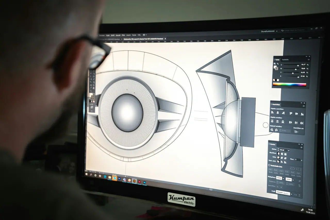
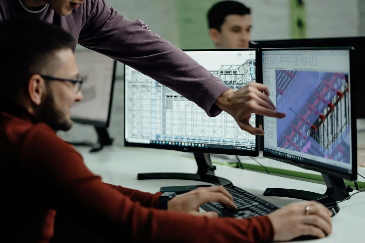
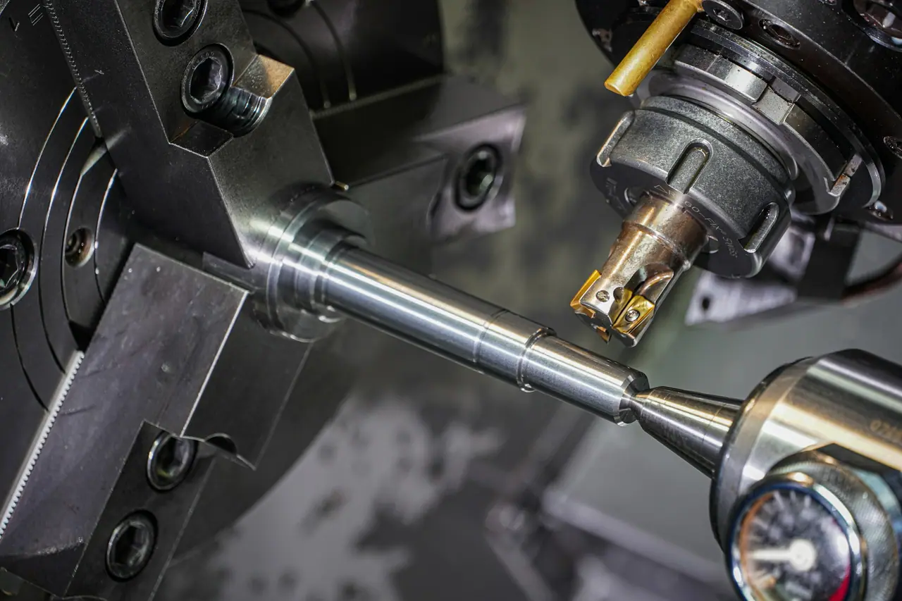
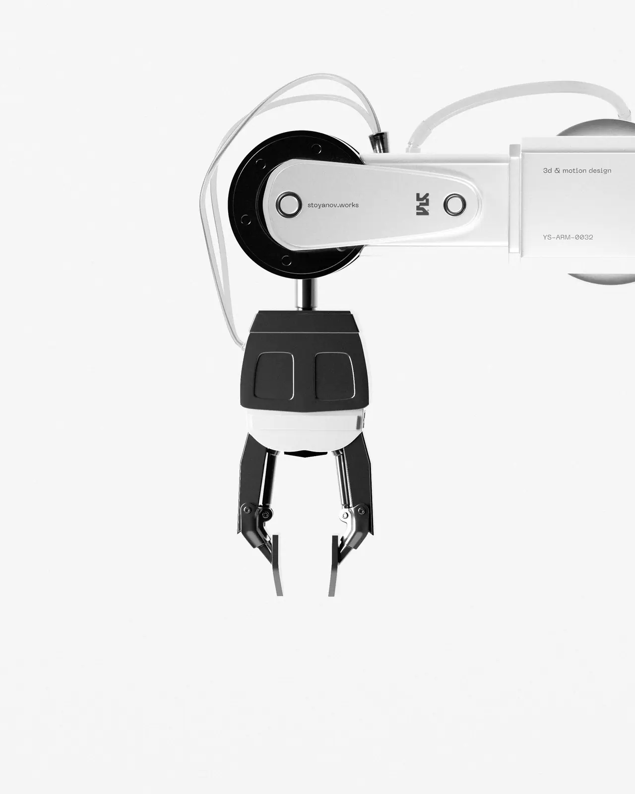


Reference visuals illustrate the field and are not RoboFab project records
Studio record
Verified workfrom the ecosystem studio
Published by the Robo 3D design studio
Verified studio work
 Studio record
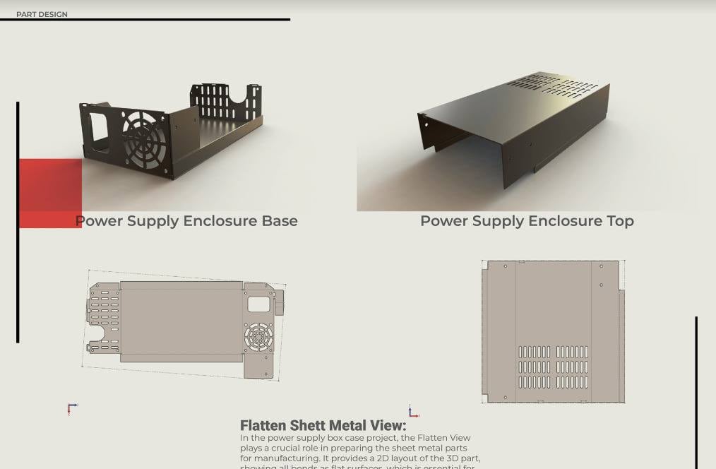
SolidWorks sheet metal
Power Supply Enclosure
Sheet metal enclosure modeled in SolidWorks with flat patterns prepared for fabrication
Robo 3D design studio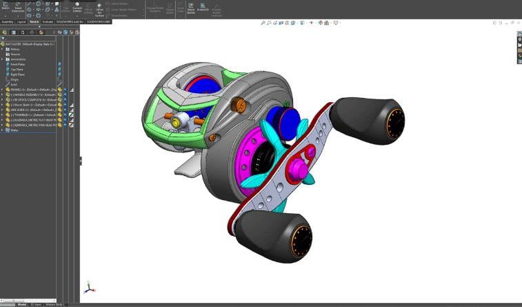 Studio record
SolidWorks assembly
Fishing Reel Assembly
Baitcasting reel built up as a full assembly of individually mated components
Robo 3D design studio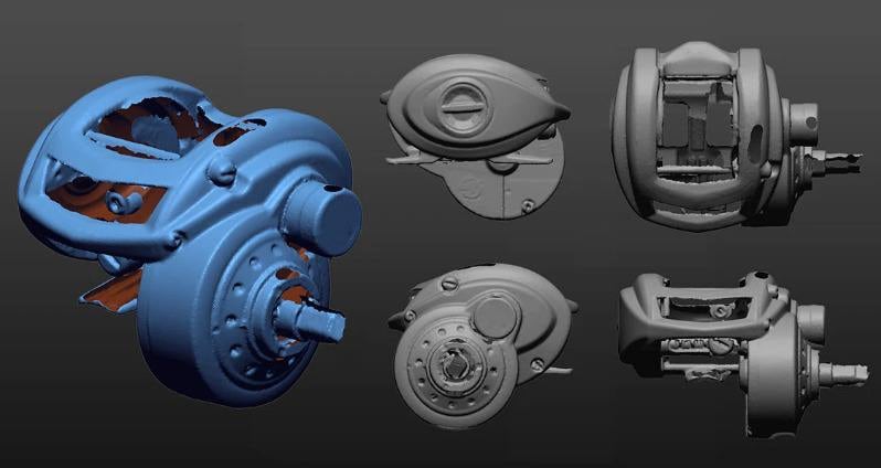 Studio record
Reverse engineering
3D Scan Reconstruction
Mesh reconstruction from a 3D scan used as reference geometry to reverse engineer a housing
Robo 3D design studio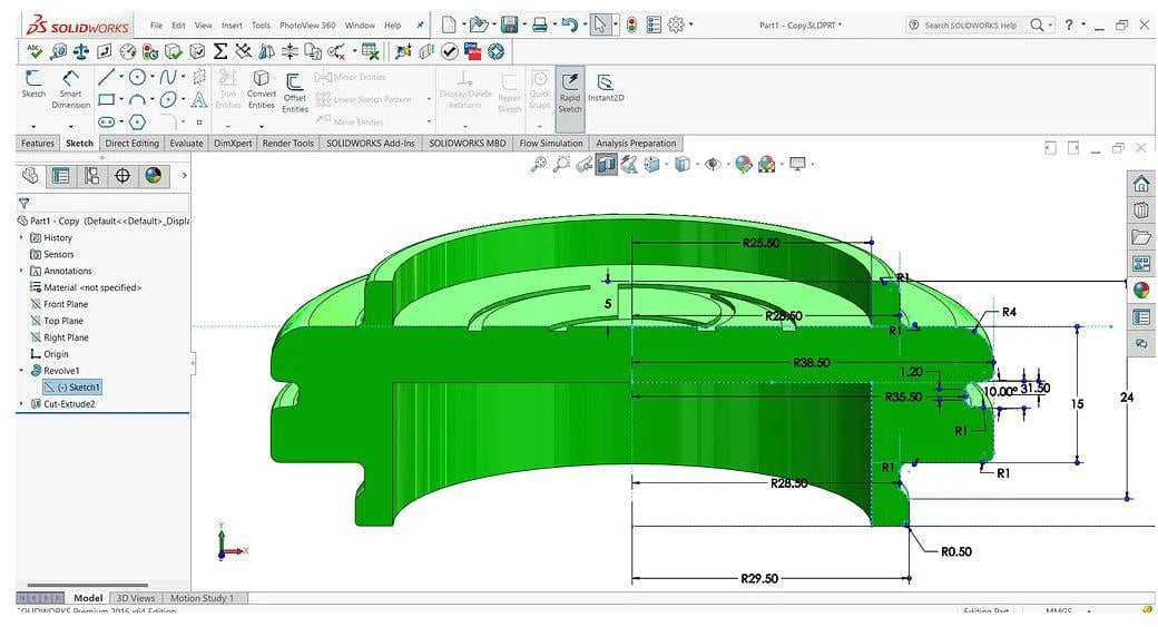 Studio record
SolidWorks part
Rotational Part Design
Dimensioned revolve sketch used to model a rotationally symmetric mechanical part
Robo 3D design studio
Engineering studies
How we wouldapproach it
Concept studies that show our methodThey are illustrations and not delivered client projects
Related engineering studies

Robotics and AutomationArtificial Intelligence
Vision Guided Sorting Cell
A camera and a trained model decide where every part belongs
Read the study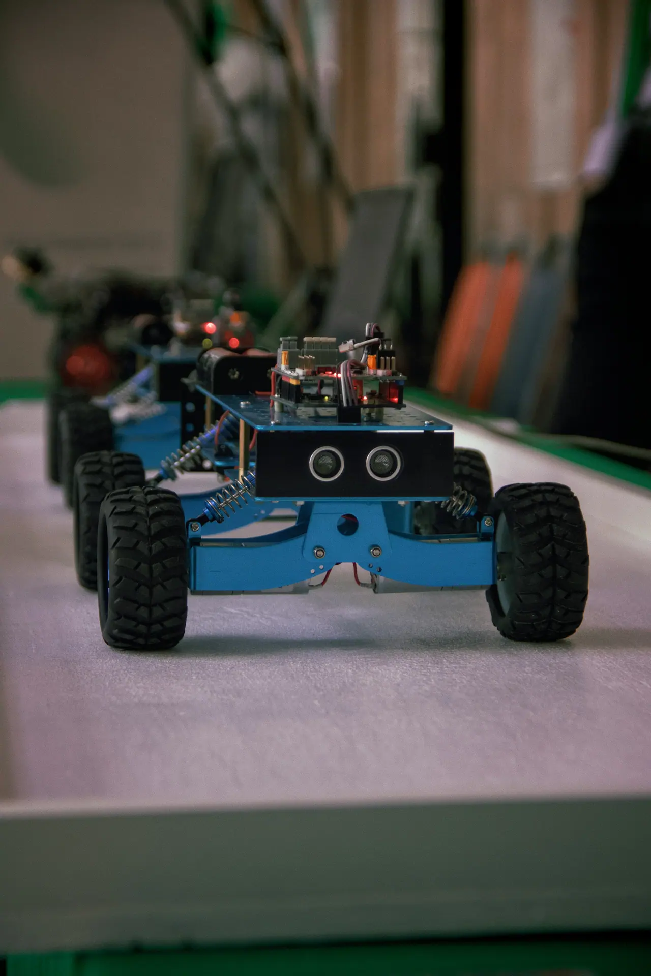
Robotics and AutomationMechanical Design
Autonomous Delivery Rover
A rugged rover that carries small loads across a campus or facility
Read the study


Works closely with
Connecteddisciplines
Related disciplines
Advanced Manufacturing
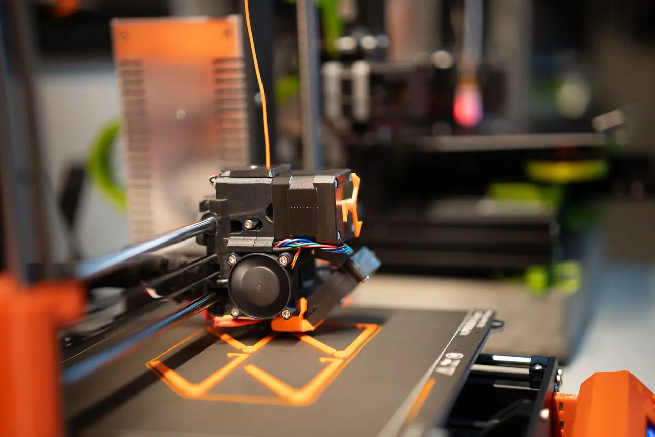
Rapid prototyping and fabrication through 3D printing
FDM printingResin printingPLAPETG
Explore the discipline
Robotics and Automation
Machines that move and sense and decide
Servo controlStepper controlPID controlInverse kinematics
Explore the discipline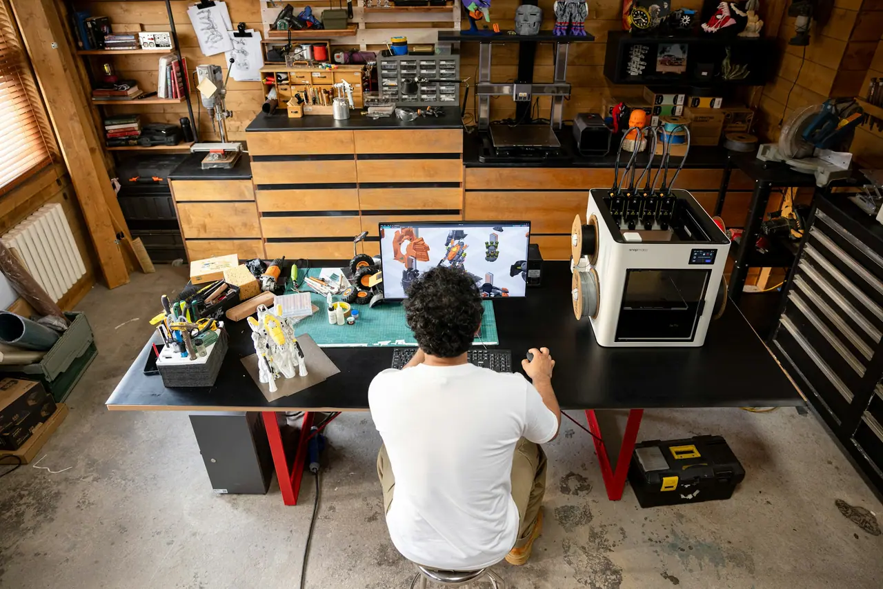
Intelligent Product Development
Mechanics and electronics and code and AI in one product
System architectureESP32Raspberry PiCustom PCBs
Explore the discipline


